Digital Oscilloscope  TDS1001c-edu

Digital Oscilloscope Tektronix TDS1001c : 40 MHz 2 Channel, TFT Color Display, 16 Automated Measurements, and FFT Analysis for Simplified Waveform Analysis. Nice disign for Education

The TDS1000C-EDU education oscilloscope series is designed specifically to meet the needs of today's schools and universities. Packed with features and built-in tools, it is easy to learn and simple to operate – ideal for first-time oscilloscope users and students. Featuring the same user interface as other members of the Tektronix TDS Oscilloscope Family, your students will learn to operate the world's most popular oscilloscope platform.
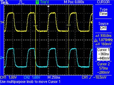
Tektronix TDS1002c
Ảnh chụp bitmap USB

Tektronix Digital Oscilloscope TDS1002c-edu
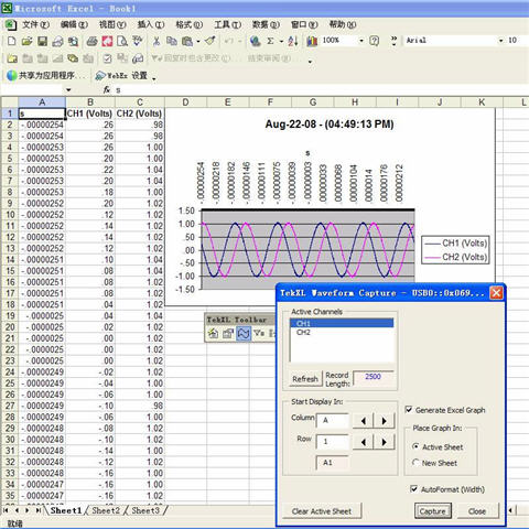
Giao tiếp với máy vi tính

Specification

Characteristic

TDS1001C-EDU

TDS1002C-EDU

TDS1012C-EDU

Display (QVGA)

Color TFT

Color TFT

Color TFT

Bandwidth*1

40 MHz

60 MHz

100 MHz

Channels

2

2

2

External Trigger Input

Included on all models

Sample Rate on each Channel

500 MS/s

1.0 GS/s

1.0 GS/s

Record Length

2.5k points at all time bases on all models

Vertical Resolution

8 bits

Vertical Sensitivity

2 mV to 5 V/div on all models with calibrated fine adjustment

DC Vertical Accuracy

±3% on all models

Vertical Zoom

Vertically expand or compress a live or stopped waveform

Maximum Input Voltage

300 VRMS CAT II; derated at 20 dB/decade above 100 kHz to 13 Vp-p AC at 3 MHz

Position Range

2 mV to 200 mV/div +2 V; >200 mV to 5 V/div +50 V

Bandwidth Limit

20 MHz for all models

Input Coupling

AC, DC, GND on all models

Input Impedance

1 MΩ in parallel with 20 pF

Time Base Range

5 ns to 50 s/div

5 ns to 50 s/div

5 ns to 50 s/div

Time Base Accuracy

50 ppm

Horizontal Zoom

Horizontally expand or compress a live or stopped waveform

*1 Bandwidth is 20 MHz at 2 mV/div, all models.

Characteristic

TDS1001C-EDU

TDS1002C-EDU

TDS1012C-EDU

I/O Interfaces

USB Ports

Included on all models: 2 USB 2.0 ports

USB host port on front panel supports USB flash drives

USB device port on back of instrument supports connection to PC and all PictBridge-compatible printers

GPIB

Optional

Nonvolatile Storage

Reference Waveform Display

(2) 2.5k point reference waveforms

Waveform Storage without USB Flash Drive

(2) 2.5k point

(2) 2.5k point

(2) 2.5k point

Waveform Storage with USB Flash Drive

96 or more reference waveforms per 8 MB

Setups without USB Flash Drive

10 front-panel setups

Setups with USB Flash Drive

4000 or more front-panel setups per 8 MB

Screen Images with USB Flash Drive

128 or more screen images per 8 MB (the number of images depends on file format selected)

Save All with USB Flash Drive

12 or more Save All operations per 8 MB

A single Save All operation creates 3 to 9 files (setup, image, plus one file for each displayed waveform)

Acquisition Modes

Characteristic

Description

Peak Detect

High-frequency and random glitch capture. Captures glitches as narrow as 12 ns (typical) using acquisition hardware at all time-base settings from 5 μs/div to 50 s/div

Sample

Sample data only

Average

Waveform averaged, selectable: 4, 16, 64, 128

Single Sequence

Use the Single Sequence button to capture a single triggered acquisition sequence at a time

Roll Mode

At acquisition time base settings of >100 ms/div

Trigger System

Characteristic

Description

Trigger Modes

Auto, Normal, Single Sequence

Trigger Types

Characteristic

Description

Edge (Rising/Falling)

Conventional level-driven trigger. Positive or negative slope on any channel. Coupling selections: AC, DC, Noise Reject, HF Reject, LF Reject

Video

Trigger on all lines or individual lines, odd/even or all fields from composite video, or broadcast standards (NTSC, PAL, SECAM)

Pulse Width (or Glitch)

Trigger on a pulse width less than, greater than, equal to, or not equal to, a selectable time limit ranging from 33 ns to 10 s

Trigger Source

CH1, CH2, Ext, Ext/5, AC Line.

Trigger View

Displays trigger signal while trigger view button is depressed.

Trigger Signal Frequency Readout

Provides a frequency readout of the trigger source.

Cursors

Characteristic

Description

Types

Amplitude, Time

Measurements

[Δ]T, 1[Δ]T (frequency), [Δ]V

Automatic Waveform Measurements

Period, Frequency, +Width, –Width, Rise Time, Fall Time, Max, Min, Peak-to-Peak, Mean, Cycle RMS, RMS, Cursor RMS, Duty Cycle, Phase, Delay.

Waveform Math

Characteristic

Description

Operators

Add, Subtract, Multiply, FFT

FFT

Windows, Hanning, Flat Top, Rectangular, 2048 sample points

Sources

CH1 – CH2, CH2 – CH1, CH1 + CH2, CH1 × CH2

Autoset Menu

Signal Type

Autoset Menu Choices

Single-button, automatic setup of all channels for vertical, horizontal, and trigger systems, with undo Autoset.

Square Wave

Single-cycle, Multi-cycle, Rising or Falling Edge

Sine Wave

Single-cycle, Multi-cycle, FFT Spectrum

Video (NTSC, PAL, SECAM)

Field: All, Odd, or Even

Line: All or Selectable Line Number

Autorange

Automatically adjust vertical and/or horizontal oscilloscope settings when probe is moved from point to point, or when the signal exhibits large changes.

Display Characteristics

Characteristic

Description

Display

QVGA color TFT

Interpolation

Sin (x)/x

Display Types

Dots, vectors

Persistence

Off, 1 s, 2 s, 5 s, infinite

Format

YT and XY

Environmental

Characteristic

Description

Temperature

Operating

0 °C to +50 °C

Nonoperating

–40 °C to +71 °C

Humidity

Operating and Nonoperating

Up to 80% RH at or below +40 °C. Up to 45% RH up to +50 °C

Regulatory

<

Characteristic

Description